

How To Use "View Cut" And "Input File" To Draw The Bending Moment And Shear In Abaqus?
Postprocessing | |
| Switch to the Visualization module, and open the file Crane.odb. Abaqus displays an undeformed shape plot of the crane model. |
- Plotting the deformed model shape
-
To begin this practice, plot the deformed model shape with the undeformed model shape superimposed on information technology. Specify a nondefault view using (0, 0, 1) as the Ten-, Y-, and Z-coordinates of the viewpoint vector and (0, 1, 0) as the X-, Y-, and Z-coordinates of the upward vector.
The undeformed shape of the crane superimposed upon the plain-featured shape is shown in Figure one.
Figure 1. Plain-featured shape of cargo crane.
- Using display groups to plot chemical element and node sets
-
You can use display groups to plot existing node and chemical element sets; you can also create brandish groups by selecting nodes or elements directly from the viewport. Yous will create a display group containing only the elements associated with the main members in truss construction A.
To create and plot a display group:
-
In the Results Tree, expand the Sections container underneath the output database file named Crane.odb.
-
To facilitate your selection, modify the view back to the default isometric view using the
 tool in the Views toolbar.
 -
In succession, click the items in the container until the elements associated with the main members in truss A are highlighted in the viewport. Click mouse button 3 on this particular and select Replace from the menu that appears.
Abaqus/CAE at present displays merely this grouping of elements.
-
To salvage this group, double-click Display Groups in the Results Tree; or use the
 tool in the Brandish Group toolbar.
The Create Display Grouping dialog box appears.
-
In the Create Display Grouping dialog box, click and enter MainA as the name for your display group.
-
Click Dismiss to shut the Create Display Grouping dialog box.
This brandish grouping now appears underneath the Display Groups container in the Results Tree.
-
- Beam cantankerous-section orientation
-
You volition at present plot the section axes and axle tangents on the undeformed model shape.
To plot the beam section axes:
-
From the chief bill of fare bar, select ; or use the
 tool in the toolbox to display simply the undeformed model shape.
 -
From the main carte bar, select ; then, click the Normals tab in the dialog box that appears.
-
Toggle on Show normals, and take the default setting of On elements.
-
In the Style area at the bottom of the Normals page, specify the Length to be Long.
-
Click .
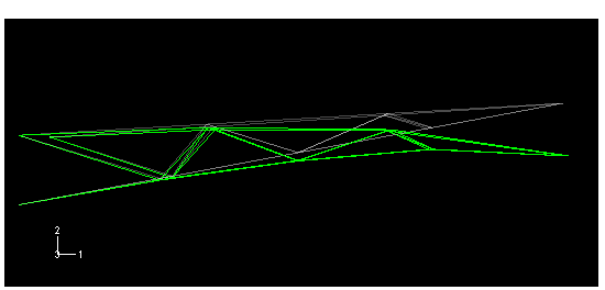
The section axes and beam tangents are displayed on the undeformed shape.
The resulting plot is shown in Figure 2. The text annotations in Figure 2 that identify the section axes and beam tangent will not appear in your image. The vector showing the local axle 1-centrality, , is blue; the vector showing the beam 2-axis, , is red; and the vector showing the beam tangent, , is white.
Effigy 2. Plot of beam section axes and tangents for elements in display group MainA.

-
- Rendering beam profiles
-
You will now brandish an idealized representation of the beam contour and contour the stress results.
To render beam profiles:
-
From the master menu bar, select .
The ODB Brandish Options dialog box appears.
-
In the General tabbed page, toggle on Render beam profiles and accept the default scale factor of 1.
-
Click .
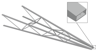
Abaqus/CAE displays beam profiles with the appropriate dimensions and in the correct orientations. Figure 3 shows the beam profiles on the whole model. Your changes are saved for the duration of the session.
-
Click
 to contour the Mises stress on the rendered contour.
Effigy three. Cargo crane with axle profiles displayed.
-
- Creating a hard copy
-
You can save the current prototype to a file for hard-copy output.
To create a PostScript file of the current image:
-
From the master menu bar, select .
The Impress dialog box appears.
-
From the Settings expanse in the Print dialog box, select Black&White equally the Rendition blazon; and toggle on File equally the Destination.
-
Select PS as the Format, and enter beam.ps as the File name.
-
Click
 .
.The PostScript Options dialog box appears.
-
From the PostScript Options dialog box, select 600 dpi as the Resolution; and toggle off Print appointment.
-
Click to utilize your selections and to close the dialog box.
-
In the Print dialog box, click .
Abaqus/CAE creates a PostScript file of the current image and saves it in your working directory as beam.ps. You can impress this file using your system's command for printing PostScript files.
-
- Displacement summary
-
Write a summary of the displacements of all nodes in brandish group MainA to a file named crane.rpt. The peak displacement at the tip of the crane in the two-direction is 0.0188 m.
- Section forces and moments
-
Abaqus can provide output for structural elements in terms of forces and moments interim on the cross-section at a given signal. These section forces and moments are defined in the local beam coordinate system. Toggle off the rendering of beam profiles, so contour the section moment nearly the beam 1-axis in the elements in display group MainA. For clarity, reset the view so that the elements are displayed in the 1–2 plane.
To create a "bending moment"-type contour plot:
-
From the list of variable types on the left side of the Field Output toolbar, select Main.
-
From the list of output variables in the heart of the toolbar, select .
Abaqus/CAE automatically selects , the outset component name in the list on the correct side of the Field Output toolbar, and displays a contour plot of the bending moment about the axle 1-axis on the deformed model shape. The deformation scale factor is chosen automatically since geometric nonlinearity was non considered in the assay.
-
Open the dialog box, and select a Uniform deformation scale cistron of 1.0.
Colour contour plots of this type typically are not very useful for one-dimensional elements such equally beams. A more than useful plot is a "bending moment"-type plot, which you tin produce using the contour options.
-
From the main carte du jour bar, select ; or apply the
 tool in the toolbox.
The Contour Plot Options dialog box appears; past default, the Bones tab is selected.
-
In the field, toggle on Show tick marks for line elements.
-
Click .
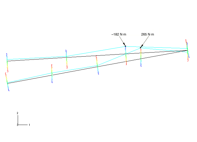
The plot shown in Effigy 4 appears. The magnitude of the variable at each node is at present indicated by the position at which the contour curve intersects a "tick mark" drawn perpendicular to the element. This "bending moment"-type plot can be used for any variable (not just bending moments) for any one-dimensional element, including trusses and axisymmetric shells besides as beams.
Effigy 4. Bending moment diagram (moment about beam ane-centrality) for elements in display group MainA. The locations with the highest stress (created by the bending of the elements) are indicated.
-

How To Use "View Cut" And "Input File" To Draw The Bending Moment And Shear In Abaqus?,
Source: https://abaqus-docs.mit.edu/2017/English/SIMACAEGSARefMap/simagsa-c-bmspostprocessing.htm
Posted by: williamssionly.blogspot.com
0 Response to "How To Use "View Cut" And "Input File" To Draw The Bending Moment And Shear In Abaqus?"
Post a Comment